Bar drilling
Introduction
This table shows the standard drillings of the output bars, customer-side, according to DIN 43673. The figure shows the drilling patterns (a total of six types) and the dimensions visible in the table, which are also repeated in drilling patterns 5 - 6. At the design phase, you can choose the type of hole pattern and the applications will defines the dimensions accordingly. You can add other types of holes or modify existing ones but you will no longer be in line with DIN standards.
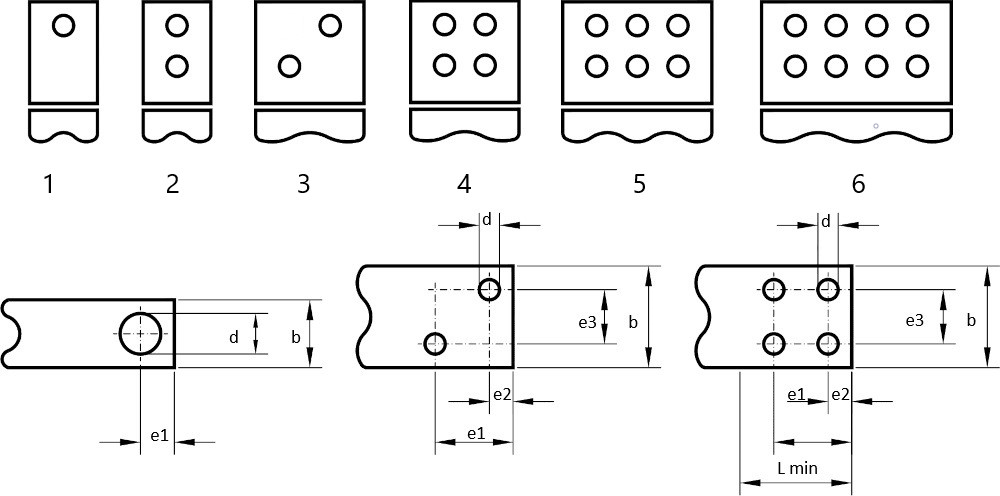
Table fields (bar drilling)
- Bar width: dimension b of the drawing above.
- Min.Length bar: dimension L min. of the drawing above. This is the minimum length to needed for the customer's attachment.
- Hole diameter: dimension *d of the drawing. All holes are equal.
- Dim. E1: distance between holes: Dimension e1 of the drawing above.
- Dim. E2: distance between holes: dimension e2 of the design above.
- Dim. E3: distance between holes: dimension e3 in the drawing above.
- Dim. A: field for future use: Enter 0.
- Drilling type: see drawing above
- Nr. holes: no. of holes on the bar. The number of holes is already implied by choosing a certain hole pattern, but it is shown for clarity.